


 English
 عربى
عربى Español


Content
- 1 What Is a High Voltage Machine Lead Wire?
- 2 Voltage Classifications and What They Mean in Practice
- 3 Insulation Materials Used in High Voltage Lead Wire
- 4 Thermal Class Ratings and Their Importance
- 5 Conductor Construction and Sizing Considerations
- 6 Relevant Standards and Certifications
- 7 Installation Best Practices for High Voltage Machine Lead Wire
- 8 Common Failure Modes and How to Avoid Them
What Is a High Voltage Machine Lead Wire?
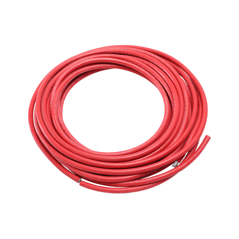
A high voltage machine lead wire is a specialized electrical conductor designed to carry high voltage current between the internal windings of an electric machine — such as a motor, generator, or transformer — and its external terminal connections, switchgear, or power supply. Unlike standard building wire or general-purpose cable, machine lead wire must simultaneously withstand the electrical stress of elevated operating voltages, the thermal stress of continuous operation in confined, heat-dense environments, and the mechanical stress of vibration, flexing, and physical contact with surrounding components inside the machine housing.
The term "lead wire" in this context refers specifically to the wire that exits the machine's stator or rotor winding assembly and terminates at an accessible connection point — typically a terminal board, conduit box, or junction box. Because this section of wiring is exposed to the full operating voltage of the machine while also being subjected to internal heat generated by winding losses, it represents one of the most demanding cable applications in industrial electrical engineering. Selecting the wrong lead wire — whether underrated in voltage class, thermally insufficient, or poorly matched to the installation environment — is a direct cause of insulation failure, ground faults, and catastrophic machine damage.
Voltage Classifications and What They Mean in Practice
High voltage machine lead wires are rated according to the maximum operating voltage they can safely carry without insulation breakdown. In the industry, voltage classification follows standardized tiers that align with the voltage levels at which electric machines are designed to operate. Understanding these classifications is the essential starting point for specifying the correct wire for any given machine application.
The most commonly referenced voltage ratings for machine lead wire in industrial applications are 600V, 1000V, 2000V, 4000V, 5000V, and 8000V (sometimes expressed as 0.6/1kV, 1/2kV, 3.6/6kV, and 6/10kV in the IEC system). The two-number IEC notation describes conductor-to-conductor and conductor-to-ground voltage ratings respectively. Medium voltage machines operating at 3.3kV, 6.6kV, or 11kV system voltages require lead wires rated well above the nominal system voltage to provide the necessary safety margin against voltage spikes, switching transients, and partial discharge phenomena that occur during motor starting and variable frequency drive operation.
It is important to note that the voltage rating of a machine lead wire must account for more than just the steady-state operating voltage. Variable frequency drives (VFDs) generate steep-fronted voltage pulses with peak amplitudes that can reach two to three times the nominal system voltage at the motor terminals, depending on cable length and drive output filter design. Lead wires in VFD-driven motor applications must be selected with this transient voltage overshoot in mind, and in many medium voltage VFD installations, inverter-duty rated wire with enhanced insulation systems is mandatory.
Insulation Materials Used in High Voltage Lead Wire
The insulation system is the defining characteristic of a high voltage machine lead wire. It must provide dielectric integrity at the rated voltage, thermal stability at continuous operating temperatures, resistance to the specific chemical and physical environment inside the machine, and sufficient mechanical toughness to survive installation and long-term service without cracking, abrasion, or compression damage.
Cross-Linked Polyethylene (XLPE)
XLPE is among the most widely used insulation materials for medium and high voltage machine lead wire. The cross-linking process converts thermoplastic polyethylene into a thermoset material with superior thermal stability — rated for continuous operation at 90°C and up to 250°C under short-circuit conditions — and excellent dielectric properties. XLPE maintains its insulating performance over a wide voltage range and is particularly valued for its low dielectric losses, which reduce heat generation within the insulation wall at high operating voltages. XLPE-insulated lead wires are standard in medium voltage motors, high-power generators, and traction machines.
Ethylene Propylene Rubber (EPR) and EPDM
Ethylene propylene rubber and its terpolymer variant EPDM offer excellent flexibility alongside strong dielectric performance. EPR-insulated lead wire is preferred in applications where the wire must flex during installation or where machine vibration creates continuous flexing stress at the lead exit point. EPR insulation has good resistance to ozone, moisture, and thermal aging, with temperature ratings typically reaching 90°C continuous and 130°C overload. It is widely used in marine motors, traction applications, and machines installed in humid or chemically contaminated environments where the insulation may be exposed to condensation or process vapors.
Silicone Rubber
Silicone rubber insulation is the choice for extreme high-temperature machine lead wire applications. With continuous ratings commonly reaching 180°C and some grades rated to 200°C or beyond, silicone-insulated lead wire is used in furnace motors, traction drives, and Class H insulation system motors where ambient temperatures inside the machine housing are too high for XLPE or EPR. Silicone insulation also provides excellent flame resistance and low smoke emission, making it preferred in enclosed spaces such as mine hoists and underground traction systems. Its limitation is relatively low mechanical toughness compared to EPR and XLPE — silicone wire requires careful handling to avoid nicking or crushing the insulation during installation.
Polyimide and Composite Tape Constructions
For the most demanding high voltage, high temperature machine applications — aerospace motors, nuclear plant auxiliaries, and specialty industrial drives — lead wires insulated with polyimide (Kapton) tape or composite mica-glass tape systems are specified. These constructions provide exceptional dielectric strength per millimeter of insulation wall thickness, allowing compact wire dimensions even at high voltage ratings. Mica-based composite systems also provide inherent fire resistance and the ability to maintain electrical integrity during a fire event, a critical safety requirement in certain traction and emergency service applications.
Thermal Class Ratings and Their Importance
Thermal class is the second critical rating parameter after voltage class. Electric machines generate heat during operation, and the internal temperature of the machine housing — the environment in which the lead wire runs — is governed by the machine's insulation class and load cycle. Specifying a lead wire with an inadequate temperature rating for the installation environment leads to accelerated insulation aging and eventual thermal failure, even if the voltage rating is correctly matched.
| Thermal Class | Max. Continuous Temp. | Typical Insulation Material | Common Application |
| Class B | 130°C | EPR, XLPE | Standard industrial motors |
| Class F | 155°C | Modified EPR, XLPE | High-duty cycle motors |
| Class H | 180°C | Silicone rubber | Traction, furnace motors |
| Class N / R | 200°C+ | Polyimide, mica composite | Aerospace, nuclear, specialty |
In practice, lead wire is typically specified one thermal class above the machine's rated insulation class to provide a design margin. A machine with a Class F winding system, for example, would commonly use Class H rated lead wire to ensure the insulation life at the actual operating temperature comfortably exceeds the expected machine service life without requiring premature rewinding or lead wire replacement.
Conductor Construction and Sizing Considerations
The conductor itself — beneath the insulation — must be correctly specified for current-carrying capacity, flexibility, and resistance to the mechanical conditions inside the machine. High voltage machine lead wires use stranded copper conductors in the majority of applications, with the stranding configuration chosen based on the flexibility requirement and the conductor cross-section.
- Class 1 and 2 (solid and standard stranded): Used where the lead wire is fixed in position after installation with no ongoing flexing. Suitable for direct runs from winding to terminal box in machines where vibration is low and the lead is clamped securely along its length.
- Class 5 and 6 (flexible fine-wire stranded): Specified where the lead wire must flex during installation, accommodate machine vibration, or allow the terminal box or lead exit point to move relative to the winding. Finer stranding distributes bending stress across more individual wires, extending the fatigue life of the conductor under cyclic flexing.
- Tinned or nickel-plated conductors: Bare copper oxidizes over time, particularly at elevated temperatures, increasing contact resistance at terminations. Tin-plating the conductor is standard practice for lead wires operating up to approximately 150°C; nickel plating is used for higher temperature applications where tin would oxidize and lose its protective function.
- Cross-section sizing: Conductor cross-section must be selected to carry the full load current within the thermal limits of the insulation system, accounting for the reduced heat dissipation available when the wire is bundled with other leads inside a confined machine housing. Derating factors for bundling, ambient temperature, and installation method must be applied, not simply the tabulated ampacity of the wire in free air.
Relevant Standards and Certifications
Compliance with recognized standards is non-negotiable for high voltage machine lead wire used in industrial, commercial, and utility electrical equipment. Standards define the test methods, performance thresholds, and quality assurance requirements that give engineers confidence that the wire will perform as specified throughout its service life.
- IEC 60317: The primary international standard series covering specifications for particular types of winding wires, including magnet wire and lead wire constructions used in motors and transformers. Relevant parts define insulation material requirements, dimensional tolerances, electrical tests, and thermal aging test protocols.
- IEC 60228: Defines the conductor construction requirements — cross-sectional areas, number of strands, and dimensional tolerances — for conductors of insulated cables, including the flexibility classes referenced in conductor specification.
- NEMA MW 1000: The North American standard for magnet wire, covering enameled and film-insulated wires used in motor and transformer windings. While primarily focused on winding wire, it provides reference data relevant to lead wire specifications in North American machine applications.
- UL 44 and UL 83: UL standards for thermoset and thermoplastic insulated wire respectively, applicable to machine lead wire sold into the North American market. UL listing is a common procurement requirement for lead wire used in equipment supplied to US and Canadian customers.
- IEEE 1553 and IEEE 275: IEEE guides for the thermal evaluation of sealed insulation systems in motors and generators, providing the test methodology framework used to validate that an insulation system — including the lead wire — will achieve the required service life at rated temperature.
Installation Best Practices for High Voltage Machine Lead Wire
Even correctly specified lead wire will fail prematurely if installed without adequate attention to routing, support, termination, and protection. The following practices represent the accumulated best practice of motor manufacturers, rewinding shops, and field service engineers working with high voltage machines.
- Minimum bend radius: Never bend high voltage lead wire below its specified minimum bend radius during installation. Excessive bending compresses the insulation wall on the inside of the bend and stretches it on the outside, reducing dielectric strength at that point and creating a stress concentration that will eventually fail under electrical load. For most medium voltage XLPE and EPR wires, the minimum installation bend radius is 6–10 times the overall wire diameter.
- Mechanical clamping and vibration isolation: Lead wires inside motor housings must be clamped at regular intervals to prevent movement under vibration. Unsupported lead wire that vibrates against metal machine components will abrade its insulation through fretting, producing localized insulation thinning that fails under voltage stress. Use non-metallic clamps or rubber-lined metallic clamps to avoid contact pressure concentrations on the insulation surface.
- Lead exit sealing: Where lead wire exits the machine housing through a gland or conduit entry, the seal must prevent the ingress of moisture, oil mist, and process contamination without creating a mechanical choke point that concentrates bending stress in the insulation. Use glands rated for the operating temperature and chemical environment of the installation, and confirm that the gland's clamping action contacts only the outer jacket or braid, never the insulation layer directly.
- Termination quality: High voltage lead wire terminations must be made using correctly sized, properly crimped or soldered lugs or connectors. Poor terminations — undersized lugs, cold solder joints, or incorrectly torqued bolted connections — create localized resistance heating that accelerates insulation degradation at the termination point. For medium voltage terminations, use stress-relief termination kits that provide the correct geometric transition from the insulation system to the connection hardware, preventing electrical field concentration at the cut end of the insulation.
- Hipot testing after installation: Before commissioning a rewound or newly installed high voltage machine, conduct a high potential (hipot) dielectric test on the complete winding and lead wire assembly. The test applies a DC or AC voltage significantly above the operating level — typically two to four times the rated voltage for a specified duration — to verify that the insulation system has no manufacturing defects, installation damage, or contamination that would cause premature failure in service. Document and retain the test results as the baseline reference for future maintenance testing.
Common Failure Modes and How to Avoid Them
Understanding the failure mechanisms of high voltage machine lead wire helps engineers and maintenance teams identify deterioration before it results in a forced machine outage or a safety incident. The following failure modes account for the majority of lead wire failures encountered in field service.
- Thermal degradation: Sustained operation above the insulation's rated temperature causes oxidative cross-linking, hardening, and eventual embrittlement of the insulation polymer. The insulation becomes brittle, develops surface cracks, and ultimately loses dielectric integrity. Prevention requires correct thermal class specification, adequate ventilation within the machine, and load management to prevent sustained overloading.
- Partial discharge erosion: At medium and high voltages, voids, contaminants, or delaminations within the insulation wall can sustain partial discharge — low-energy electrical discharges that do not immediately bridge the insulation but progressively erode the insulation material through chemical and physical attack. Over time, partial discharge channels grow until full insulation breakdown occurs. Using insulation systems rated above the operating voltage by an adequate margin and ensuring void-free termination are the primary preventive measures.
- Mechanical abrasion: Lead wire insulation rubbing against sharp metal edges, other wires, or clamping hardware during vibration progressively removes insulation material until conductor exposure occurs. Thorough mechanical clamping, edge protection grommets, and routing away from potential contact points are essential preventive measures at installation.
- Moisture and chemical contamination: Water, oil, and process chemicals that penetrate the insulation system reduce its dielectric strength and accelerate thermal aging. Selecting insulation materials with appropriate chemical resistance, maintaining proper machine sealing, and conducting routine insulation resistance (Megger) testing during preventive maintenance intervals allow early detection of contamination-related degradation before failure occurs.


